A repair
I am the proud owner of
6 TP-Link TL-PA211 AV200 Mini Powerline Adapters. And if it weren't for the hack described in this post, I would have been the owner of 6
broken TL-PA211 ethernet over powerline adapters. Within a period of a year after purchase all of them died. Not a single one survived. What were the symptoms ?
- No more LED's
- A rather high noise emitting from the unit
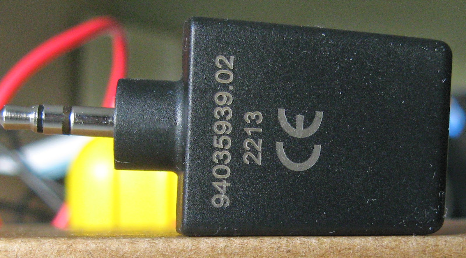
This image shows the unit:
Front:
Back:
By the way, the 200 Mbps is obviously invented by somebody in the marketing department thinking that 100 megabit rx + 100 megabit tx is a reason to call this a 200 megabit device while any sane human being would call it 100 Mbps full duplex.
To continue, find the screw under the sticker (warning: this will void your warranty ...):
And next use a flat screwdriver to open the six plastic clips on the side as shown in the image below:
Then you are very likely to notice that one of the largest capacitors has a swollen vent (and possibly some dried residue) as shown in the image below:
If you are a bit handy with a soldering iron you can simply replace these through-hole electrolytic capacitors with a similar version simply purchase a 6.3V 1500 uF (microfarad) from your local electronics parts shop and you're good to go. To remove the PCB from the plastic cover pull the plastic on the side. After soldering to mount the PCB again in the plastic case bend the metal clips which will fit the metal pins of the socket under a downwards angle and push them in.
Some more images illustrating the broken and replacement parts:
After this replacement I haven't seen a single failure (and the fixed ones are running for several months now).
Architecture
And while we're at it, let's take a look at what's actually under the hood. If we look at one of the earlier images:
There are some obvious chips present:
- Realtek RTL8201CP, which is a 10/100M Fast Ethernet Phy, which is the direct connection between the RJ-45 plug and the Atheros chipset, this is U5 on the picture
- Etrontech EM638165TS-6G is a 64 megabyte (8 megabyte) SDRAM running at 166 MHz, this is U9 on the picture.
But the actual magic happens in two Atheros chips. On one side you have the biggest which is the Atheros INT6400AIG (MAC/PHY IC aka the digital part, U7 on the picture) and its companion the Atheros INT1400 (Line driver IC, aka the analog part, U8 on the picture).
The following image is borrowed from the INT6400 AV Chipset product brief (which I kindly uploaded to
scribd:
Meaning the entire datapath is something like:
Powerline <-> INT1400 <-> INT6400 <-> RTL8201 <-> RJ45
Obviously the product brief does not contain all the details we're interested in. The INT6400 chip package doesn't hide there's some ARM insid but the product brief doesn't mention it, but I haven't been able to find a full datasheet of that specific chip. In any case the TP-Link PA211 looks as if it's very likely a carbon copy (with bad parts selection) of the reference design.